
PDF Version
Notes
For the most up-to-date and current installation
instructions, please visit our website at
www.owlvans.com
• Please read all instructions carefully before installing
Owl products on your vehicle.
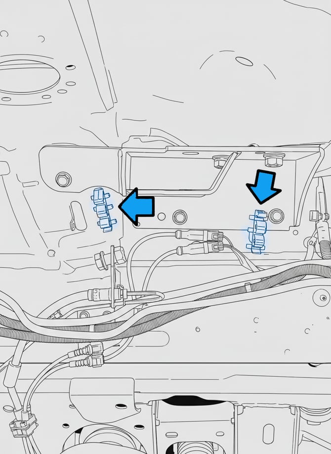
• This is a bolt-on shock kit designed for easy
installation using basic hand tools.
• NOTE: Additional steps are required for installation
on vehicles equipped with the HD rear A/C option,
which includes refrigerant lines running down the
passenger-side wheel well. Refer to step 36 for
details.
• Removal and trimming of the plastic inner fender
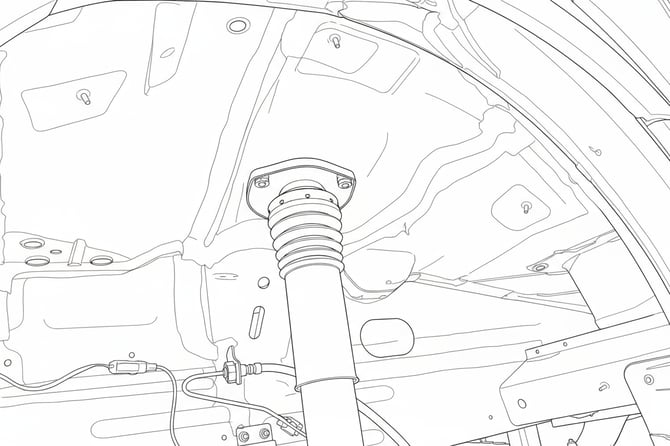
well liner is necessary for installation.
• This shock kit is fully removable, allowing the vehicle
to be returned to its original stock configuration if
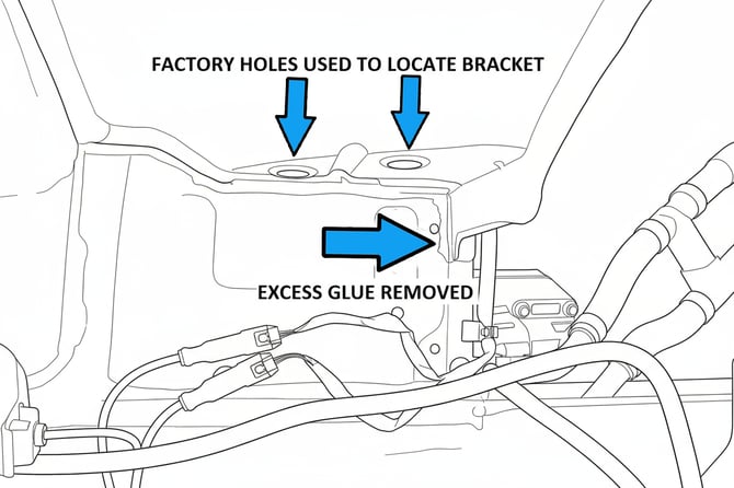
desired.
Parts List
2007-Up, Mercedes Sprinter 4x4, AWD Front Upper Shock Mount
| PART | P/N | QTY | ✔ |
|---|---|---|---|
| MERCEDES SPRINTER VS30 4X4, FRONT LH UPPER SHOCK MOUNT | SP-FUSM-D | 1 | |
| MERCEDES SPRINTER VS30 4X4, FRONT RH UPPER SHOCK MOUNT | SP-FUSM-P | 1 | |
| DRIVER NUT PLATE | SP-FUSM-DNP | 1 | |
| PASSENGER NUT PLATE | SP-FUSM-PNP | 1 | |
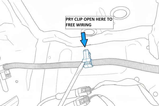
| REAR NUT PLATE | FUSM-NP | 2 | |
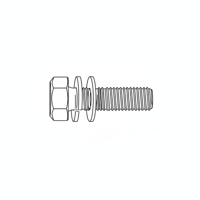
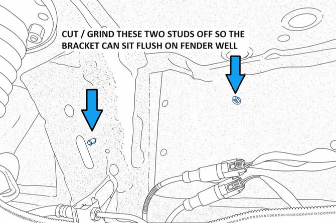
| 1/2-13 UNC, GR8, HEX HEAD BOLT X 1-1/2 in LONG | — | 3 | |
| 1/2-13 UNC, GR8, HEX HEAD BOLT X 1.0 in LONG | — | 1 | |
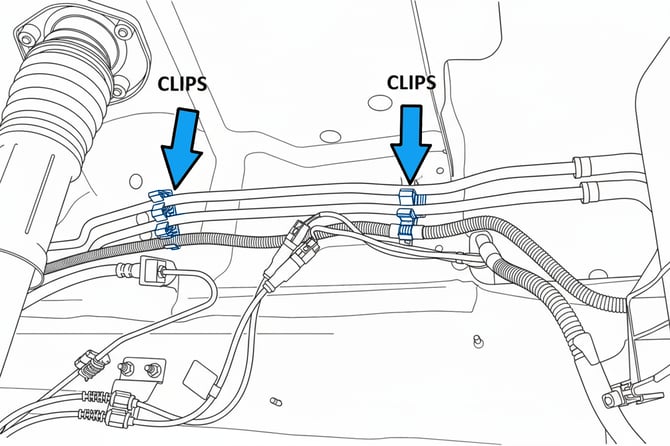
| 1/2 in GR8 FLAT WASHER | — | 5 | |
| 1/2 in GR8 LOCK WASHER | — | 3 | |
| 3/8-16 UNC X 1 in LONG, GR8, HEX HEAD BOLT | — | 6 | |
| 3/8-16 UNC STOVER NUT | — | 4 | |
| 3/8 in GR8 FLAT WASHER | — | 10 | |
| 3/8 in GR8 LOCK WASHER | — | 2 |
2007-Up, Mercedes Sprinter 4x4, AWD Front Lower Shock Mount
| PART | P/N | QTY | ✔ |
|---|---|---|---|
| MERCEDES SPRINTER 4X4, FRONT LOWER SHOCK MOUNT DRIVER | SP-FLSM-D | 1 | |
| MERCEDES SPRINTER 4X4, FRONT LOWER SHOCK MOUNT PASSENGER | SP-FLSM-P | 1 | |
| 9/16-12 UNC X 3.0 in LONG, GR8, HEX HEAD BOLT | — | 2 | |
| 9/16-12 UNC STOVER NUT | — | 2 | |
| 9/16 in GR8 FLAT WASHER | — | 4 | |
| M10-1.50 X 70MM LONG, GR10.9, HEX HEAD BOLT | — | 2 | |
| M10-1.50 X 40MM LONG, GR10.9, HEX HEAD BOLT | — | 4 | |
| M10-1.50 STOVER NUT | — | 6 | |
| M10 FLAT WASHER | — | 10 |
2015-Up, Mercedes Sprinter 4x4, AWD Adjustable Front Shocks
| PART | P/N | QTY | ✔ |
|---|---|---|---|
| MERCEDES SPRINTER 4X4, OWLxFALCON ADJUSTABLE FRONT SHOCKS |
20-01-33-311-210, 20-01-33-312-210 |
2 |
Tools Needed
1. Quality jack and two jack stands
2. Basic hand tools:
• Wrench and socket set, including:
• Metric sizes: 10mm, 13mm, 16mm, 17mm
• SAE sizes: ½”, 13/16”, 7/8”
3. Automotive trim removal tool
4. Drill equipped with a 3/8” (10mm) metal-cutting drill bit
5. Hammer and chisel
6. Cutting tools for trimming the plastic inner fender well:
• Tin snips
• 4-1/2” angle grinder or 3” pneumatic cutoff tool
• Die grinder or Dremel-type rotary tool
Installation
These instructions show installation on the driver’s (left-hand)
side. Passenger side installation is similar; any differences will
be noted in the steps.
1.
Loosen lug bolts then safely support the vehicle on an
appropriate lift or jack stands so the front suspension can
hang freely. Ensure the support method follows the vehicle
manufacturer’s specifications.
2.
With the suspension supported, remove the front wheels and
tires. Factory lug bolts typically have a 19mm head.
3.
Remove the inner fender well liners by first removing the two
push pins located near the front lower portion of the bumper.
These connect the liner to the bumper.
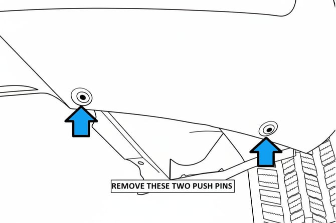
4.
Using an automotive trim removal tool, carefully lift under the
head of the push pin, then under the body, to remove it fully.
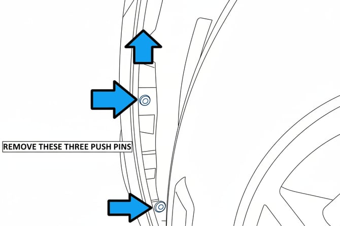
5.
Inside the fender well, remove the three push pin fasteners
near the outer bumper lip.
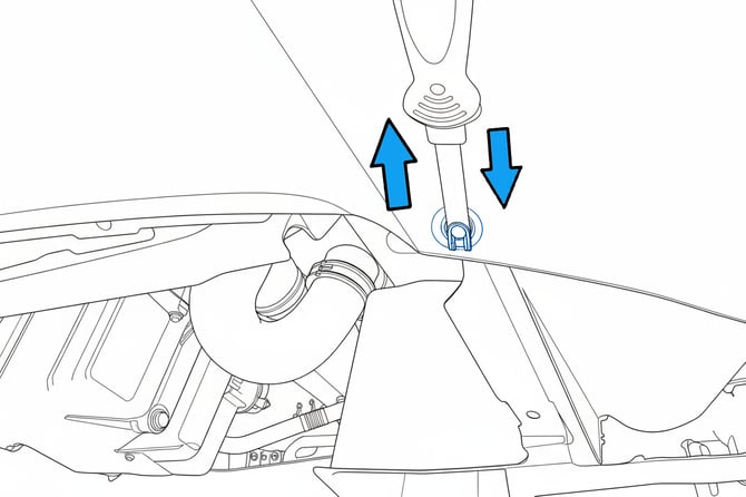
6.
Locate and remove the three plastic nuts securing the front
half of the inner fender liner to the chassis with a 10mm
socket.
7.
Remove the mudflap by taking out the two T-25 torx screws
and two 10mm plastic nuts securing it. All fasteners shown
with blue arrows in the referenced images must be removed
for mudflap removal.
a. One 10mm plastic nut is located underneath the
vehicle towards the center of the wheel well (see
reference image).

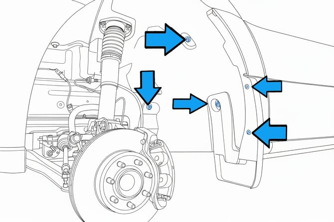
8.
Remove the final two plastic 10mm nuts securing the rear half
of the liner to the chassis (denoted with Blue arrows in
image).
9.
Remove the rear half of the liner by pulling it off the studs and
out from under the fender lip.
10.
Remove the front half of the liner by pulling the edge from
under the bumper cover and fender lip, rotating down to
clear studs, then removing completely.
11.
Position the lower shock mount (part no. 102301) so the
gusset plate of the bump stop mount on the lower control
arm lines up.
12.
Remove the two lower bolts from the front gusset with a
16mm socket/wrench. Loosen the upper bolt about three
turns without fully removing it.
a. For 2023+ AWD vans, loosen both upper bolts
three turns.

13.
Install the lower shock mount as indicated. The mounts are
side-specific. Use the provided M10-1.5 x 40mm bolts in the
gusset, with washers under both the bolt head and stover nut.
Start all bolts but do not fully tighten.
a. Install the M10-1.5 x 70mm bolt from the bottom of
the control arm up through the slotted hole near
the pivot bushing, with a washer under the bolt
head only.

14.
Once all hardware is started, snug bolts. Use a 17mm socket/
wrench for new bolts and a 16mm for re-tightening the
gusset’s upper bolt.
a. Torque all hardware to 43 ft-lbs (58 N·m).
b. Repeat the process for the passenger side.
15.
Insert the appropriate upper nut tab into the fender well (see
image for correct orientation)

16.
From the engine bay, position the nut tab so its threads align
with the chassis hole and the plate sits flat. Welds should be
on the top side.
a. Driver-side nut tab installs on the flat fender spot
near the ABS module.

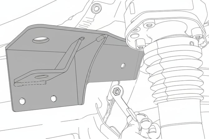
17.
Install the upper shock bracket for the driver's side. These are
side-specific and oriented only one way. Use a lock washer
under the bolt head, then a flat washer.
18.
Ensure the bracket sits flat. If factory glue/undercoating
prevents this, carefully remove excess material so it sits flush.
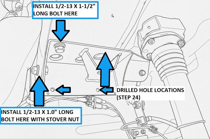
19.
Install the ½-13 x 1-1/2” bolt in the outer upper mounting
hole.
a. Start the ½-13 x 1” bolt in the forward hole with
washers under the bolt head and stover nut.
20.
Use the rear nut tab to attach the rear of the bracket as shown.
Avoid dropping it inside the chassis.
21.
Install the provided 3/8-16 x 1” bolt with lock and flat washers.
Snug it using a 9/16” socket/wrench.
22.
Snug the front ½-13 bolts with a ¾” socket. Do not fully
tighten.
23.
Mark and drill the two lower mounting holes using a 3/8”
(10mm) bit, ensuring no wiring or accessories are behind
the drill locations.
24.
Install the provided 3/8-16 x 1” bolts with washers under both
bolt head and stover nut. Snug hardware.
25.
Fully tighten hardware
a. Torque upper ½-13 bolts to 50 ft-lbs (68 N·m).
b. Torque 3/8-16 bolts to 20 ft-lbs (27 N·m).
26.
Steps 27–29 apply to 2015–2022 4WD vans. Steps 30–31
apply to 2023+ AWD vans.
27.
For passenger side 4WD, locate and free the wiring above the
ABS/wheel speed sensor wiring. Remove clips from studs.

28.
Smooth down threaded studs where wiring was attached,
then apply paint to bare metal.
29.
Continue per vehicle year instructions.
30.
For 2023+ AWD, remove the two front clips from the chassis
with a trim tool. Retain as these will be reused.
31.
Remove clips from DEF/ABS lines.
32.
Install passenger bracket in same sequence as driver side.
Remove excess glue if needed so bracket sits flush. Insert
upper nut tab aligned with mounting holes, welds facing up.

33.
Refer to steps 22–26 to finish passenger bracket installation.
34.
Clips from Step. 30 are reused. The rear clip is put back in the
hole it was removed form. The front clip is put in the hole in
the upper shock bracket. (2023+ AWD)
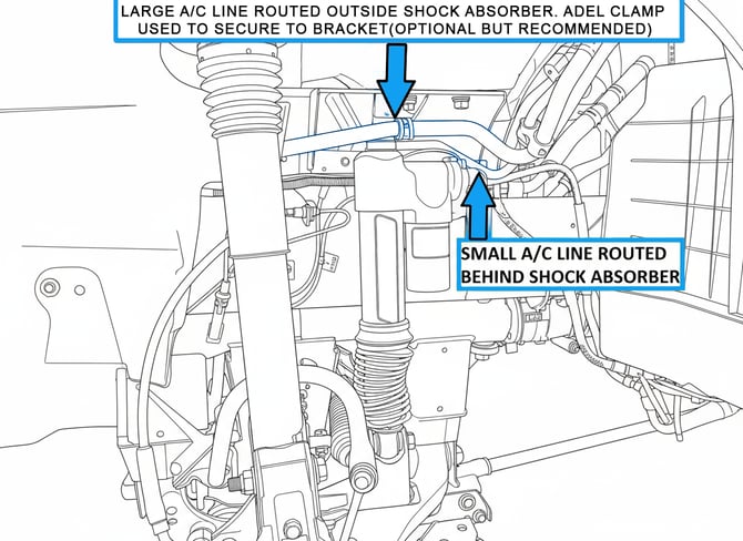
35.
For HD rear A/C vehicles, route A/C lines and fit shock as
shown in reference image.
37.
Install shocks in lower mount first using 9/16-12 x 3.0” bolt,
with washer under head and stover nut.
39.
Snug lower bolt with 13/16” socket/wrench on head and 7/8”
on nut. Do not fully tighten.
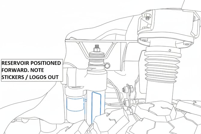
40.
For Falcon Adjustable Piggyback shocks, note side-specific
orientation. Compress and position properly, reservoir toward
front. Torque lower bolt to 100 ft-lbs (135 N·m)
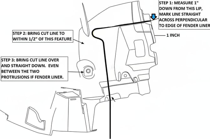
41.
Trim front half of factory liner as shown in image. Smooth
edges after trimming.
42.
Test-fit liner ensuring no contact with shock/reservoir.
43.
Rear half of liner needs no trimming.
44.
Reinstall liners and secure ABS/sensor wiring.
45.
Reinstall wheels/tires. Torque wheel studs per OEM spec:
• 2500 SRW: 170 ft-lbs (231 N·m)
• 3500 DRW: 140–150 ft-lbs (190–200 N·m
• Owl Wheels: 135ft-lbs (183.1 N·m)
46.
Check shock clearance after lowering the vehicle.
47.
After 100 miles, recheck bolt torques.
Congrats!
Your Installation is complete.
RELEASE OF LIABILITY
I, the customer, do hereby release and forever discharge Owl Vans LLC, their agents, employees,
successors and assigns, and their respective heirs, personal representatives, affiliates, successors and assigns, and any and all persons, firms or corporations liable or who might be claimed to be liable, whether or not herein named, from any and all claims, demands, damages, actions, causes of action or suits of any kind or nature whatsoever, whether known or unknown, fixed or contingent, which I now have or may hereafter have or claim to have, as a result of or in any way relating to the following: Parts sold & installed by Owl Vans LLC or parts sold & installed by end-user; any parts sold online, any parts sold online or installed by a re-seller, any parts installed by an installation shop.
It is understood and agreed that this payment is made and received in full and complete settlement and satisfaction of the aforesaid actions, causes of action, claims and demands; that this Release contains the entire agreement between the parties; and that the terms of this Agreement are contractual and not merely a recital.
Furthermore, this Release shall be binding upon the undersigned, and his respective heirs, executors, administrators, personal representatives, successors and assigns. This Release shall be subject to and governed by the laws of the State of Arizona.
PRODUCT SAFETY WARNING:
Owl Vans LLC strongly recommends the installation of products be done by a certified mechanic. If
this does not occur, be certain the person(s) installing the product read, understand and follow all
instructions and warnings pertaining to the application before installation. Do not add, alter, or
fabricate any factory or aftermarket parts to increase vehicle height over the intended height of the Owl Vans LLC product purchased. Mixing component brands is not recommended.
Installation of suspension lift kits or any other lifting kits or devices will raise the center of gravity. For this reason, Owl Vans LLC urges that extreme caution be used when encountering driving conditions which may cause vehicle imbalance. Furthermore, the driver’s field of vision and judgment will not be as good due to the height of the vehicle. Due to the installation of larger tires, the speedometer will read slower than the actual speed being traveled and more distance will be required to stop the vehicle. It is the owner’s responsibility to caution and warn any potential driver of the vehicle about these driving and handling conditions. Owl Vans LLC will not be held liable or responsible for damages or personal injuries resulting from the use of lifting devices and or related products. The tires and rims should be changed to sufficiently increase the vehicle’s total overall width and stability to help accommodate lifting devices.
Owl Vans LLC aftermarket suspension products and accessories modify a vehicle for uses which
exceed conditions anticipated by the vehicle manufacturer. The uses include the high performance
demands required during off-road. These conditions vary in the degree of extremity and cannot be
controlled by the vehicle or product manufacturer. If the components within the suspension system or accessories become worn due to frequent and/or extreme use, the safety and reliability of the vehicle is at risk. The maintenance of aftermarket equipment to ensure the vehicle occupants safety is entirely your responsibility. Do not purchase Owl Vans LLC products unless you are willing to accept this responsibility. Do not install any Owl Vans LLC suspension products or accessories unless you feel competent at installing the product without causing present or future injury to yourself or other vehicle occupants; seek an authorized installation center.
Most states have some type of law limiting vehicle height. The amount of lift allowed, and how the lift can be achieved, varies greatly. Several states offer exemptions for farm and commercial registered vehicles. It is the vehicle owner’s responsibility to check state and local laws to ensure that their vehicle will be in compliance.
Owl Vans LLC reserves the right to make changes in design, materials and specifications as deemed necessary without prior notice and without assuming obligation to modify any product previously manufactured. Obligation or liabilities will not be assumed with respect to similar products previously advertised.
This Release of Liability and Product Safety Warning has been read and fully understood by the
undersigned and has been explained to me.